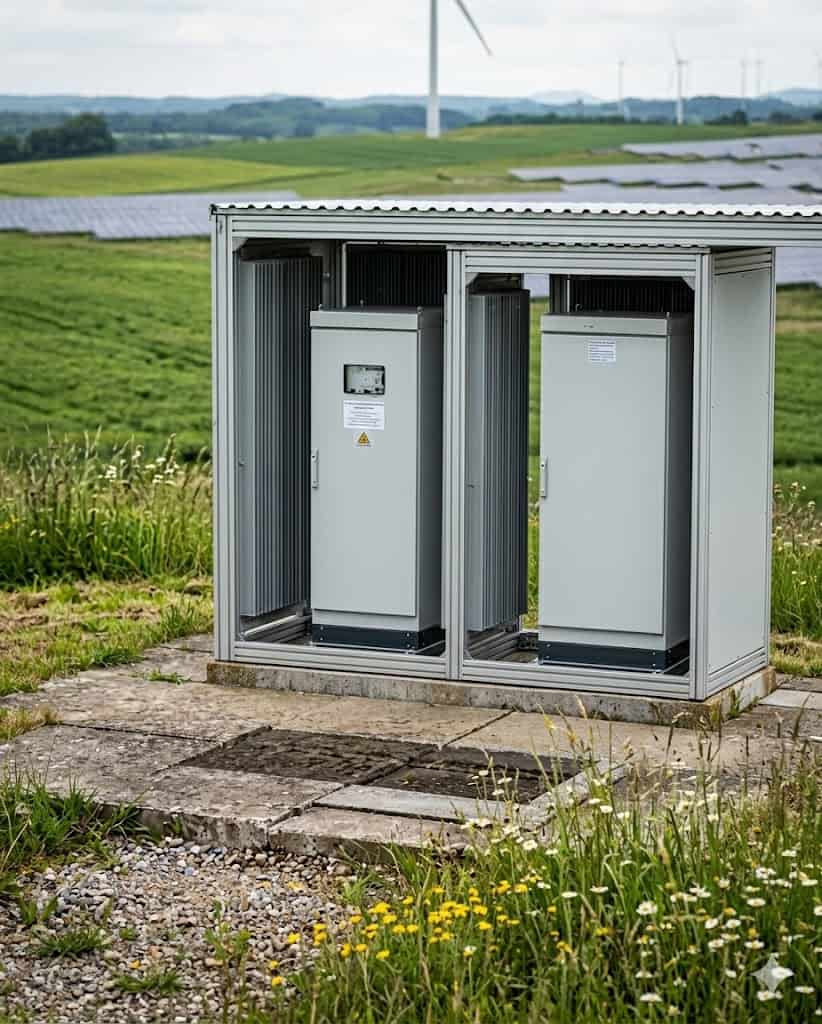
Reduce MV cable length and installation effort in large-scale renewables
Using branch joint technology for smarter collector design
MV collector system design has a direct impact on cable routing, component count and installation effort. As projects scale up, small design choices can quickly translate into higher costs, longer installation time and increased installation effort on site
Conventional loop-based designs are widely used and technically proven, but they are not always the most efficient approach at larger scale. An alternative method can reduce cost and installation effort while maintaining control and reliability. Further down this page, you can access the full engineering guide for a more detailed explanation.
Typical impact for large-scale projects
In large-scale solar, wind and BESS projects, small design choices can have a significant impact on overall cost, layout and execution.
Using a more direct collector system approach can help reduce:
• Total MV cable length
• The number of cable terminations and switchgear units
• Installation effort and planning
• Overall system cost and required components
Conventional collector system design
Traditional collector systems are typically based on loop-in/loop-out configurations or rely on multiple switchgear locations throughout the network. These approaches are well-established and technically sound, but they also introduce additional cable routing, more terminations and higher system cost and more installation effort.
In larger projects, this results in:
- Increased cable length across the system
- More components such as switchgear and terminations
- Greater installation effort and coordination on site
The Lovink Solution
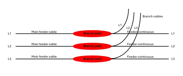
Lovink’s branch joint technology enables a different approach to MV collector system design by allowing a continuous feeder with direct connections to each asset.
Instead of routing cables through every station, the system becomes more direct and structured. This reduces cable routing, limits the number of required components and simplifies the overall system layout, particularly in larger renewable energy projects.
With this approach, the main feeder remains continuous while individual assets are connected via branch connections. Protection and switching functionalities remain unchanged, while the collector layout itself becomes simpler and more direct.
What changes in practice
Less cable required
A more direct collector system layout reduces the need for looping cables between assets. This leads to a shorter overall cable length, particularly in larger projects where distances quickly add up.
Fewer components in the system
With fewer required connections, the number of components such as switchgear and terminations can be reduced. This results in a more straightforward system design.
More straightforward installation
A simpler layout with fewer components makes installation easier to organise and execute. This can reduce the overall effort required on site during construction.
Want to see what this means for your project?
Every project is different. The actual impact depends on layout, scale and system requirements.
Application in renewable energy projects
This approach can be applied across different renewable energy projects, where collector system design directly impacts layout, cost and execution.
Solar parks
In solar projects, this approach supports more efficient string layouts by reducing the need to loop between inverter-transformer stations.
Wind farms
For wind farms, where distances between turbines are typically larger, a more direct layout helps reduce unnecessary cable routing.
BESS installations
In BESS projects, where systems are often built in phases, assets can be connected without reconfiguring the main feeder.
Relevant across project roles
The impact of this approach differs per role within a project, depending on responsibilities in design, execution and cost control.
For EPC contractors
Simplifies installation and reduces on-site complexity, supporting more efficient planning and execution.
For developers and asset owners
Supports a more cost-efficient collector system design with fewer components and a more scalable setup.
For engineers
Provides a cleaner and more structured system layout, making design and planning more straightforward.
Download the full engineering guide
Want to explore this approach in more detail?
Fill in your details below to access the full engineering guide and see how it can be applied in practice. The guide provides additional insight into collector system design, application and practical considerations.